01. Project Overview
A hexapod is a six-legged robotic platform that uses coordinated leg movements to navigate different types of terrain.
This project involved designing the complete mechanical CAD assembly of an 18-degree-of-freedom hexapod robot, with three degrees of freedom per leg.
The primary focus was to develop a mechanical structure that integrates servo motors, articulated joints, and custom-designed leg components into a cohesive robotic platform.
Rather than relying entirely on conventional servo brackets, I explored a more integrated structural design with curved leg geometry and a distinctive hexagonal central body.
Project scope
- Complete mechanical CAD assembly
- Six-legged, 18-DOF configuration
- Servo integration and joint arrangement
- Custom leg and foot geometry
- 3D-printable component design
Tools: Autodesk Fusion 360
Actuation: 18 × MG996R servo motors
Material: PLA for 3D-printed components
02. Design Objective
The challenge was to design a mechanical structure capable of accommodating 18 servo-driven joints without making the overall assembly unnecessarily bulky or complicated.
The design needed to address several considerations:
- Integrating three degrees of freedom into each leg.
- Positioning the servo motors within the available mechanical structure.
- Designing joints that allow the required articulation.
- Creating a central body that accommodates all six legs.
- Developing custom geometry suitable for 3D printing.
- Designing feet intended for ground contact and traction.
The goal was to create a cohesive mechanical platform where the individual components work together as one assembly.
03. Mechanical Architecture
An 18-DOF configuration
The robot uses six legs, each with three degrees of freedom, resulting in 18 independently actuated joints.
Each leg follows a three-joint architecture:
Coxa: Connects the leg to the central body and provides the first axis of movement.
Femur: Forms the intermediate structural link and connects the coxa assembly to the lower leg.
Tibia: Forms the lower leg section and terminates at the ground-contact foot.
This arrangement provides three degrees of freedom per leg and forms the mechanical foundation of the robot.
- Legs
- 06
- Degrees of freedom / leg
- 03
- Independently actuated joints
- 18
04. Central Body Design
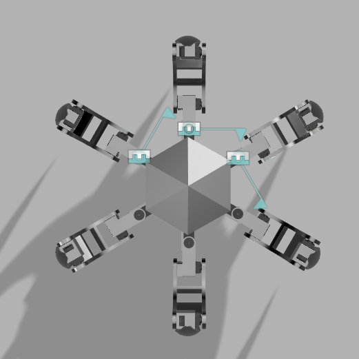
A hexagonal foundation
The central body uses a hexagonal geometry, with six mounting positions arranged around the structure.
This arrangement provides a dedicated mounting region for each leg while maintaining a compact central assembly.
The body geometry was designed around the six-legged configuration, with consideration for the placement of the servo-driven leg assemblies.
The central body also establishes the overall proportions and mechanical identity of the robot.
05. Leg Mechanism Development
Designing the articulated structure
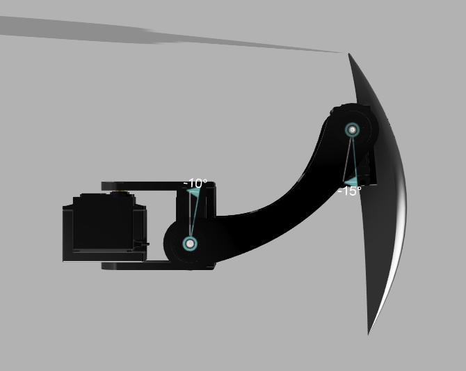
The leg assembly was one of the most important parts of the mechanical design.
I explored curved structural geometry rather than using a collection of simple straight brackets. This gives the legs a distinctive silhouette while accommodating the mechanical connections and servo housings.
The design integrates:
- Servo mounting locations.
- Articulated joint connections.
- Curved structural members.
- Intermediate mechanical supports.
- A dedicated foot structure.
The leg geometry was developed as part of the complete mechanical assembly, allowing its proportions and connections to be evaluated in relation to the central body.
06. Servo Integration
18 independently actuated joints
The mechanical architecture is designed around 18 MG996R servo motors.
Servo placement was an important design consideration because each motor contributes to the overall dimensions, weight distribution, and packaging of the leg assembly.
The CAD design incorporates the servo housings into the mechanical structure, with mounting and connection arrangements designed around the individual joints.
This integration was intended to reduce reliance on separate mounting structures and create a more cohesive assembly.
07. Foot Design
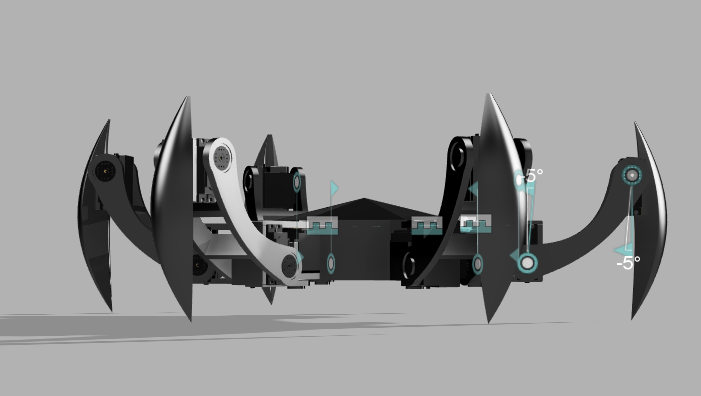
Designed for ground contact
The foot was designed as a distinct component of the leg mechanism, with a pointed, curved profile.
Its geometry was developed with ground contact and traction in mind.
Rather than treating the foot as a simple extension of the tibia, I considered it an important part of the robot's overall mechanical design and visual identity.
Actual traction and ground-contact performance will need to be evaluated through physical testing.
08. Design for 3D Printing
From CAD geometry to manufacturable components
The mechanical structure was developed with FDM 3D printing in mind.
The design process considered the geometry of individual components, servo integration, joint connections, and the need to assemble multiple printed parts into one functional structure.
PLA was selected as the material for the planned printed components.
The next stage of development will involve evaluating print tolerances, component strength, joint clearances, and assembly fit through physical prototypes.
09. Complete Mechanical Assembly
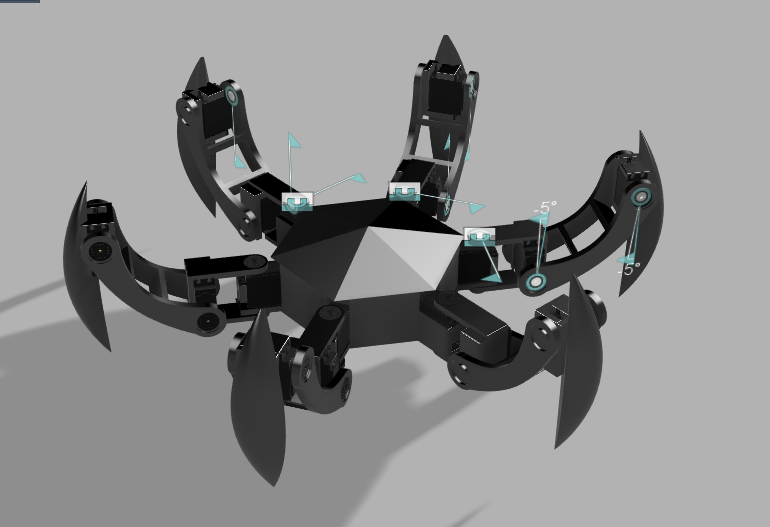
The final CAD assembly brings together the hexagonal central body, six articulated legs, servo mounting arrangements, and custom foot geometry.
The result is a complete mechanical representation of the proposed hexapod platform.
The design establishes the physical foundation for future development of the robot's electronics, power distribution, and locomotion system.
Current milestone: Complete mechanical CAD assembly.
10. What's Next?
With the mechanical design completed, the next stage is to move towards a physical prototype.
Planned development areas include:
- 3D printing and assembly of the mechanical components.
- Servo calibration and movement validation.
- Power distribution for 18 servo motors.
- Controller and electronics integration.
- Development of coordinated hexapod walking patterns.
- Testing stability, load capacity, and locomotion.
11. Key Learnings
This project helped me explore the relationship between mechanical design, component integration, and manufacturing constraints.
Designing an 18-DOF robotic platform required thinking beyond individual components and considering how the complete assembly would fit together.
It also reinforced the importance of designing mechanical systems with future assembly, prototyping, and testing in mind.
HEXAPOD — Building the mechanical foundation for a multi-legged robotic platform.